
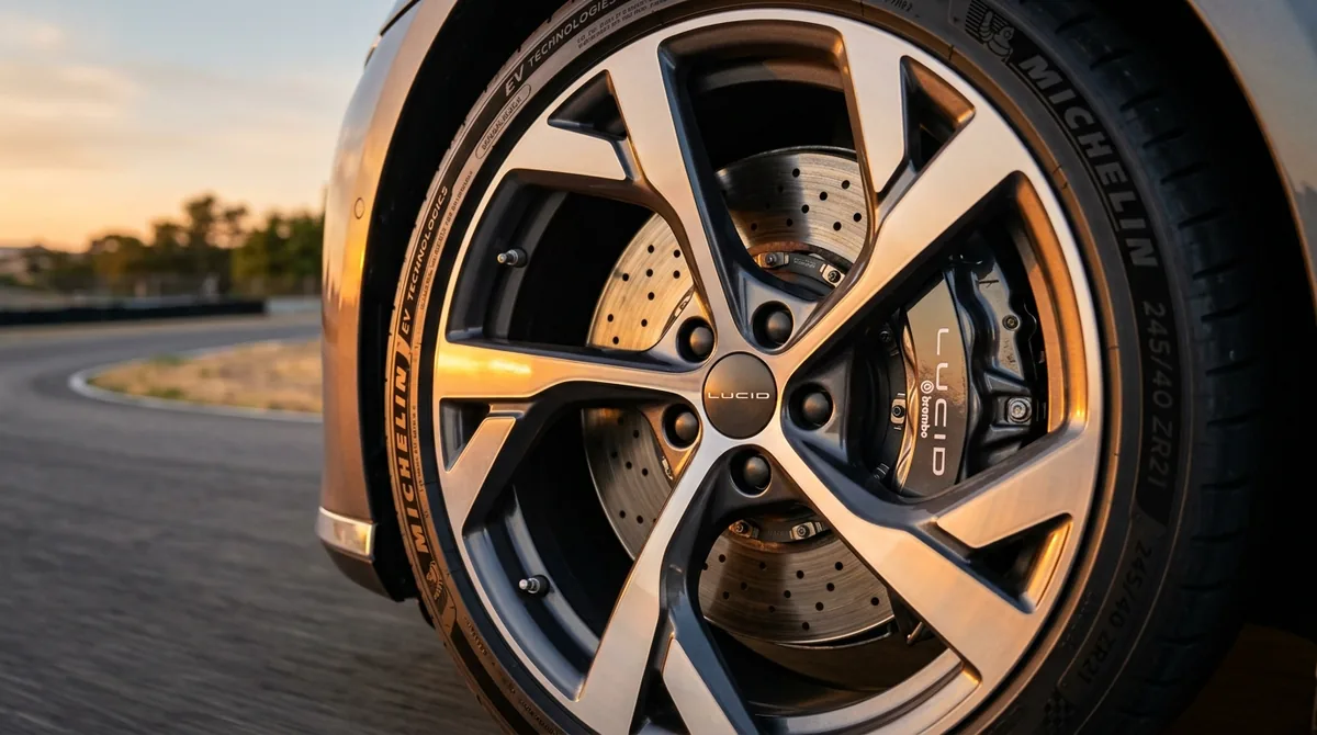
The Fundamentals of Kinetic Energy Harvesting
In conventional internal combustion engine (ICE) vehicles, stopping requires dissipating kinetic energy into thermal waste. Hydraulic calipers force friction pads against rotating cast-iron rotors, converting vehicle momentum entirely into ambient heat through mechanical friction ($Q = \frac{1}{2}mv^2$). For a two-ton vehicle travelling at 100 km/h (27.8 m/s), braking to a dead halt destroys approximately 770 kilojoules of energy.
Electric vehicles (EVs) utilize regenerative braking to recapture a substantial fraction of this energy. Rather than using mechanical pads as the primary decelerator, the vehicle's traction inverter reverses the electrical phase angle delivered to the stator windings, transforming the permanent magnet or induction traction motor from an energy consumer into an electrical generator.
Propulsion Mode:
[High-Voltage Battery] ── Direct Current ──> [Inverter] ── 3-Phase AC ──> [Motor] ── Torque ──> [Road Wheels]

Regenerative Deceleration Mode:
[Road Wheels] ── Momentum ──> [Motor as Generator] ── 3-Phase AC ──> [Inverter (Rectification)] ── DC Charge ──> [Battery]
Motor Physics: Counter-Electromotive Force and Torque Direction
Modern EV drivetrains primarily utilize Interior Permanent Magnet Synchronous Motors (IPMSM) or AC Induction Motors. During acceleration, the inverter generates a rotating magnetic field in the stator that leads the magnetic orientation of the rotor, pulling the rotor forward and applying driving torque.
When the driver lifts off the accelerator pedal or depresses the brake pedal:
- The vehicle control unit (VCU) commands the inverter to adjust the pulse-width modulated (PWM) switching frequencies so the stator field lags behind rotor rotation.
- The permanent magnets on the spinning rotor induce high-voltage alternating currents within the stationary stator windings through Faraday's Law of Induction.
- This creates a strong Counter-Electromotive Force (Back-EMF) and a negative magnetic drag torque opposing wheel rotation.
- The generated three-phase alternating current flows into the inverter's insulated-gate bipolar transistors (IGBTs) or silicon-carbide (SiC) MOSFETs, which rectify the current into high-voltage direct current (DC) and route it back into the lithium-ion traction pack.
Round-Trip Regeneration Efficiency
The net energy recovered during a regenerative braking event never reaches 100% due to thermodynamic and electrical loss cascades across each transfer junction:
- Tire-to-Road Interface & Aerodynamics: Mechanical rolling resistance and air drag dissipate 5% to 15% of kinetic energy before braking begins.
- Drivetrain & Differential Transmission: Planetary reduction gearsets exhibit 95% to 98% mechanical efficiency.
- Motor Generator Efficiency: Electromechanical conversion incurs copper stator resistance losses ($I^2R$) and iron core eddy-current hysteresis, achieving 88% to 93% efficiency.
- Inverter Rectification: Modern Silicon Carbide (SiC) inverters convert AC to DC at 96% to 98% efficiency.
- Battery Interfacial Charge Acceptance: Lithium-ion cells exhibit internal ohmic impedance, yielding an electrochemical round-trip charge acceptance efficiency of 90% to 95%.
Compounding these transfer stages yields an empirical round-trip regenerative braking efficiency of 65% to 75%. In stop-and-go urban driving cycles (such as the EPA UDDS cycle), this recaptured energy extends total driving range by 15% to 25% compared to coast-and-friction operation.
Blended Hydraulic Braking Systems
To guarantee passenger safety across emergency stops and variable road conditions, EVs combine regenerative deceleration with conventional hydraulic friction brakes via an electro-hydraulic brake-by-wire booster (such as Bosch iBooster or Continental MK C1):
- Torque Blending: During light-to-moderate pedal depression, the system applies 100% regenerative braking while hydraulic caliper pressures remain near zero.
- Seamless Transition: If the driver initiates an emergency panic stop exceeding the peak power rating of the motor generator (e.g., decelerations exceeding $0.3g$ to $0.4g$), or if vehicle speed drops below 5 km/h where Back-EMF collapses, the control computer seamlessly meters hydraulic fluid into the calipers to ensure maximum stopping force.
- ABS/ESP Coordination: If wheel speed sensors detect tire slip on ice or loose gravel, regenerative braking is instantly throttled in under 10 milliseconds, deferring wheel slip control exclusively to the Anti-Lock Braking System.
Battery Limiting Conditions: Cold Temperatures and High SoC
Regenerative braking capability is not constant; it is dynamically limited by the battery management system (BMS) under two specific operational conditions:
- High State of Charge (SoC > 90%): A battery pack charged to 95% or 100% has virtually no chemical headroom to accept high-current charge pulses (often reaching 50 kW to 150 kW during aggressive stops) without exceeding cell maximum voltage thresholds ($4.2V$ to $4.35V$ per cell). In this state, regeneration is suppressed, and deceleration relies strictly on friction pads.
- Sub-Freezing Cell Temperatures ($< 0^\circ\text{C}$): Cold ambient temperatures dramatically slow the diffusion velocity of lithium ions through the liquid electrolyte and into the graphite anode matrix. Forcing high-current charging into freezing cells causes metallic lithium plating on the anode surface, creating internal dendritic short-circuits and permanent capacity degradation. The BMS automatically clamps regeneration power until battery thermal conditioning circuits warm the pack above $15^\circ\text{C}$.