
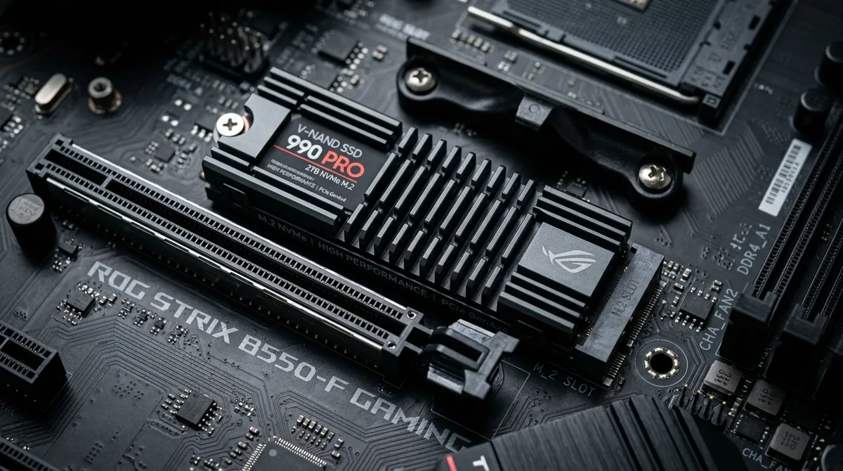
The evolution of consumer solid-state storage across PCIe 3.0, 4.0, and 5.0 bus architectures has driven sequential transfer speeds from 3,500 MB/s to over 14,000 MB/s. However, cramming enterprise-grade data throughput into an ultra-compact M.2 2280 stick generates immense localized thermal density. During prolonged sequential read/write operations—such as video rendering, large database migrations, or game asset streaming—an uncooled NVMe controller can exceed 100°C within 45 seconds, triggering aggressive thermal throttling that collapses performance down to legacy hard-drive speeds.
The Dual Thermal Paradox: Controller vs. NAND Flash
Managing NVMe solid-state drive thermals requires understanding a fundamental physical paradox: the two primary components on an SSD PCB demand diametrically opposed thermal environments:
- The ASIC Memory Controller: The microchip brain executing Wear Leveling, Garbage Collection, and NVMe command queues. Modern multi-channel controllers draw 6 to 12 watts of electrical power over a die size under 150 $mm^2$. The controller must be kept as cool as possible (ideally below 70°C); exceeding 85°C triggers immediate safety throttling.
- NAND Flash Memory Cells (V-NAND / 3D TLC): Flash storage cells operate on electron tunneling through floating gates. Cold NAND flash is chemically resistant to electron injection: programming cold flash cells requires higher write voltages, accelerating oxide degradation and prematurely exhausting write endurance. NAND flash actually prefers warm operating temperatures (between 40°C and 60°C) during write cycles.
| Component | Target Operating Temperature | Max Safe Threshold | Consequence of Overheating |
|---|---|---|---|
| NVMe Controller | 45°C – 70°C | 85°C | Severe thermal throttling, I/O timeouts, drive drops offline |
| NAND Flash Dies | 40°C – 60°C | 75°C | Thermal wear; freezing temperatures accelerate gate oxidation |
| DRAM Cache Buffer | 35°C – 65°C | 80°C | Minor throughput degradation |
Overcooling NAND flash down to room temperature with sub-ambient cooling is counterproductive; the engineering goal of an SSD heatsink is specifically to draw concentrated heat away from the controller while maintaining the NAND flash at an optimal, stable operating equilibrium.
NVMe Thermal Throttling Curves
The NVMe specification incorporates a standardized thermal management architecture (Thermal Management Temperature 1 and 2, TMT1/TMT2):
- Normal State (<70°C): Full PCIe link width and maximum lane throughput (e.g., PCIe 4.0 x4 running at full 7,000 MB/s).
- Light Throttle (TMT1, ~75°C–80°C): The controller firmware throttles internal clock cycles, introducing artificial microsecond wait states between command execution. Sequential speeds drop by 25% to 40% (down to ~4,500 MB/s) to arrest thermal climbing.
- Heavy Throttle (TMT2, >85°C): The controller slashes PCIe throughput by up to 80% (dropping to SATA-level speeds, 500–800 MB/s). If junction temperatures approach 95°C, the drive initiates an emergency shutdown to prevent permanent silicon detachment, resulting in OS kernel panics or blue-screen system crashes.
Thermal Interface Material (TIM) and Heatsink Installation
Installing an effective aftermarket M.2 heatsink requires mechanical precision:
- Component Height Discrepancy: On many SSDs, the controller die sits noticeably lower than the adjacent NAND flash packages. Placing a single uniform thermal pad across the entire PCB leaves a fatal microscopic air gap above the controller—the exact chip that generates 80% of the drive's thermal load.
- Pad Thickness Matching: Use tiered thermal pads (e.g., a 1.5 mm pad over the controller and a 1.0 mm pad over the NAND dies) to ensure firm, uniform physical compression across all surfaces without warping the delicate PCB substrate.
- Convective Airflow Requirements: Aluminum extrusion heatsinks with vertical fins cannot cool an SSD through passive radiation alone. Ensure at least gentle convective airflow from case intake fans across the M.2 region to continuously exhaust dissipated heat.