
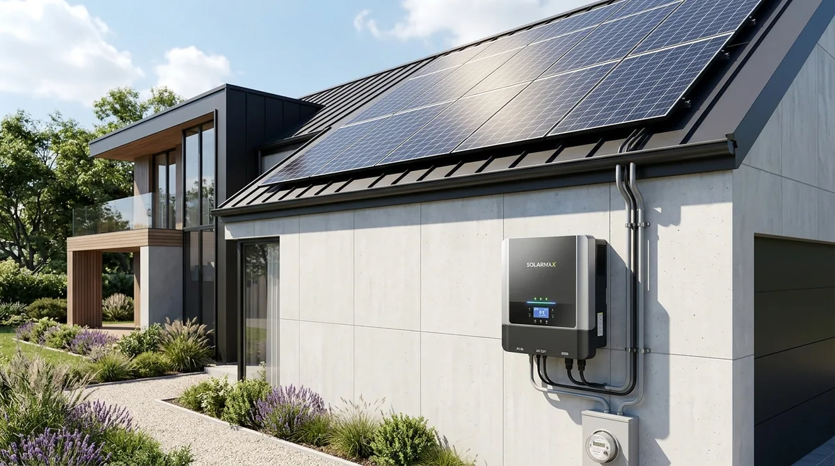
When homeowners evaluate rooftop solar photovoltaic (PV) proposals, they are frequently puzzled to discover that a 10 kW DC solar panel array is paired with an inverter rated for only 7.6 kW or 8 kW AC output. Homeowners instinctively assume that the installer is cutting corners or throttling their solar production. In reality, deliberately undersizing the inverter relative to nameplate DC panel capacity is an established, mathematically sound engineering practice known as optimizing the Inverter Loading Ratio (ILR) or DC-to-AC ratio.
The Inverter Loading Ratio (ILR): Why Oversizing DC Makes Sense
Solar panels are rated under Standard Test Conditions (STC): 1,000 $W/m^2$ solar irradiance, a pristine cell temperature of 25°C, and an air mass ratio of 1.5. Real-world operating conditions rarely match these laboratory benchmarks:
- Thermal Degradation: Solar cell voltage drops as panels heat up in direct sun (-0.35% to -0.40% power loss per degree Celsius above 25°C). On an 85°F (29°C) summer day, rooftop panels routinely operate at 55°C to 65°C, reducing actual DC output by 12% to 16%.
- Soiling and Intersystem Losses: Dust accumulation, cable resistance, and inverter conversion losses reduce real-world output by another 4% to 8%.
- Azimuth and Solar Angle: Roof planes are rarely oriented at the mathematically perfect tilt and azimuth angle.
Consequently, a 10 kW DC array rarely produces more than 8 kW to 8.5 kW of actual DC power, and achieves that peak for only 60 to 90 minutes around solar noon on clear days.
Understanding Inverter Clipping Losses
If an installer pairs a 10 kW DC array with a 1:1 ratio 10 kW AC inverter:
- The inverter operates at partial load (30% to 60% capacity) for 95% of daylight hours, where inverter conversion efficiency is lower.
- The homeowner pays hundreds of dollars extra for oversized inverter hardware and thicker electrical copper wire gauges.
By designing to an optimal DC-to-AC ratio of 1.20 to 1.30:
- The inverter ramps up to its peak efficiency threshold much earlier in the morning and sustains maximum output through the late afternoon.
- During intense midday summer sun, power exceeding the inverter's AC rating is shaved off—a phenomenon termed clipping.
| DC-to-AC Ratio (ILR) | Inverter Capacity (for 10 kW DC Array) | Typical Annual Energy Gain | Typical Annual Clipping Loss | Optimal Economic Sweet Spot? |
|---|---|---|---|---|
| 1.00 | 10.0 kW AC Inverter | Baseline | 0.0% | No (expensive, poor shoulder generation) |
| 1.15 | 8.7 kW AC Inverter | +4.2% total kWh | <0.2% | Viable, but conservative |
| 1.25 | 8.0 kW AC Inverter | +7.8% total kWh | ~0.8% to 1.2% | YES: Maximum financial ROI |
| 1.45 | 6.9 kW AC Inverter | +9.1% total kWh | 4.5% to 6.0% | Over-clipped; thermal wear on inverter |
Mathematical modeling by NREL demonstrates that the additional energy harvested during shoulder morning and afternoon hours far outweighs the minor 1% clipping losses surrendered at peak midday.
Maximum Power Point Tracking (MPPT) and Voltage Windows
Beyond capacity ratios, string inverter design requires strict electrical matching of string voltage to the inverter's MPPT operating window:
- Minimum MPPT Voltage: The string voltage on the hottest summer day ($V_{mp}$ at 65°C) must remain comfortably above the inverter's minimum tracking threshold; otherwise, the inverter drops offline.
- Maximum Open-Circuit Voltage ($V_{oc}$): Under freezing winter conditions, solar cell voltage surges. In accordance with National Electrical Code (NEC Article 690.7), the array's temperature-adjusted $V_{oc}$ at the record-low local winter temperature must NEVER exceed the inverter's maximum input voltage ceiling (typically 500V or 600V DC). Exceeding this limit causes instantaneous dielectric breakdown of inverter input transistors.