
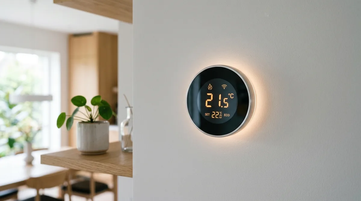
The Continuous Power Demands of Smart Thermostats
Traditional mercury bulb and mechanical bimetallic thermostats operated as simple passive switches. When ambient room temperature dropped below the setpoint, a mechanical contact closed the circuit between the red power wire (R or Rh) and the heating call wire (W), allowing 24 volts alternating current (VAC) from the HVAC furnace transformer to energize the gas valve relay. Because these legacy thermostats drew zero electrical power for themselves, they functioned seamlessly over a simple two-wire or four-wire copper bundle without needing an electrical return path.
Modern smart thermostats, by contrast, are full-fledged embedded computers equipped with backlit liquid crystal displays, 2.4 GHz and 5 GHz Wi-Fi transceivers, ambient humidity sensors, and occupancy radar. Maintaining persistent network connectivity and driving color user interfaces requires an uninterrupted electrical current of 100 to 300 milliamperes at nominal 24VAC. Supplying this continuous power without tripping HVAC control boards requires an understanding of low-voltage alternating current distribution.
The Role of the Common (C) Wire
In North American low-voltage HVAC control wiring (governed by ANSI/AHRI Standard 540), control power originates from a step-down transformer mounted inside the furnace or air handler. This transformer converts 120VAC household mains voltage into nominal 24VAC secondary voltage:
- R Wire (Red): Represents the "hot" leg of the transformer secondary winding (24VAC relative to common).
- C Wire (Blue or Cyan): The "Common" leg representing the electrical ground or neutral return of the secondary transformer coil.
- W Wire (White): Auxiliary heat / primary furnace stage call.
- Y Wire (Yellow): Air conditioning compressor relay call.
- G Wire (Green): Blower fan relay call.
When a thermostat is wired with only R and W (heating) or R, W, Y, and G, the circuit only closes when active heating or cooling is demanded. Without a dedicated C wire, there is no closed return path back to the secondary coil for the thermostat's internal logic boards when the furnace or air conditioner is idle.
+---------------------------------------------------------+
|                  HVAC Control Circuit                   |
|                                                         |
|  24VAC Transformer Hot (R) -----> Thermostat Power IC   |
|                                         |               |
|  24VAC Transformer Com (C) <----+-------+               |
|                                 | (Dedicated Return)    |
|                                                         |
|  Furnace Heat Relay (W) <-------+ (Switched Output)     |
+---------------------------------------------------------+
The Pitfalls of "Power Stealing" Architecture
To accommodate older residences with pre-existing 4-wire bundles, early smart thermostat manufacturers designed "power stealing" (parasitic harvesting) circuitry. When the HVAC system is idle, the thermostat draws a micro-current through the Y (cooling) or W (heating) relay coils back to the transformer ground. The current is kept deliberately small—typically below 20 milliamperes—aiming to stay under the pull-in threshold of mechanical relays.
However, modern high-efficiency HVAC equipment utilizes sensitive solid-state microprocessors and digital control boards rather than robust electro-mechanical coil relays. Parasitic power stealing frequently triggers severe operational pathologies:
- Relay Chattering and Short-Cycling: The parasitic leakage current partially charges capacitors on the furnace control board, causing the gas ignition solenoid or fan contactor to chatter rapidly, leading to premature component failure.
- Boiler Pulsing: Hydronic zone valves receive phantom trigger currents, causing boiler circulator pumps to cycle intermittently every few minutes during mild weather.
- Battery Depletion During Extreme Weather: During protracted winter freezes or summer heatwaves, the heating or cooling call wire remains continuously energized at 24VAC. While energized, voltage differential across the parasitic shunt drops to zero, starving the smart thermostat of recharge current and causing sudden Wi-Fi disconnection or complete shutdown.
Safe Installation Options for 4-Wire Homes
When an inspection of the thermostat wall plate reveals only four conductors (R, G, Y, W) and no unused copper strands tucked behind the drywall, technicians have three reliable resolution paths:
1. The Add-a-Wire Diode Multiplexer Adapter
The most robust retrofit without pulling new cabling is an OEM power extender kit (such as the Fast-Stat or Ecobee PEK). This device installs directly inside the furnace blower cabinet:
- The kit takes standard
YandGthermostat signals and multiplexes them over a single physical copper conductor using forward and reverse AC half-wave diode rectification. - This frees up the existing physical green conductor to serve as a dedicated, true 24VAC Common line (
C) connected straight to the furnace transformer. - The indoor blower and cooling compressor retain completely independent operational control without signal collisions.
2. G-Wire to C-Wire Reassignment (Temporary Workaround)
If an immediate fix is required and summer cooling is not utilized (heating-only furnace), the unused G (fan) wire can be disconnected from the blower relay at both the wall plate and the furnace control board and re-landed directly onto the C terminal. The thermostat then handles fan operation automatically through the furnace heat sequencer.
3. Pulling New 18/5 or 18/8 Thermostat Cable
For long-term reliability and multi-stage heat pump compatibility, replacing aged 18/4 wiring with direct-burial or CL2-rated 18/8 solid copper thermostat wire remains the gold standard. Extra conductors provide future-proof support for two-stage compression (Y1/Y2), auxiliary emergency heat strips (W2/AUX), and whole-home dehumidifier control (DEHUM).
Practical Diagnostic Checklist
Before energizing any smart thermostat installation:
- Cut mains power to the furnace at the primary service disconnect switch or circuit breaker.
- Verify with a digital multimeter set to AC volts that
RtoCmeasures between 24.0VAC and 28.5VAC. - Ensure the transformer fuse (typically an automotive-style 3A or 5A blade fuse on the control board) is intact.
- Verify that jumper clips between
RcandRhare removed if your property uses separate transformers for heating and cooling.