
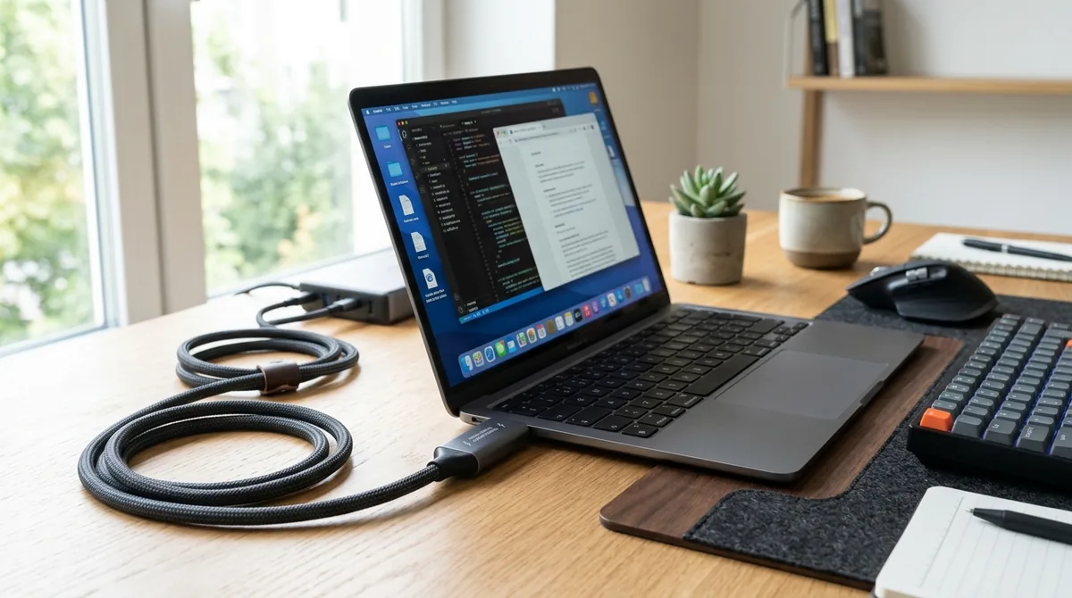
The universal standardization of the reversible 24-pin USB Type-C connector has unified charging across smartphones, tablets, high-performance laptops, and power tools. However, behind the simple physical plug lies an extraordinarily complex digital communications bus. Plugging a 240W high-output charger into a fragile smartphone must never deliver 48 volts to a 5-volt battery; delivering destructive voltage would trigger instant silicon destruction. The safety and versatility of USB charging is governed by the rigorous cryptographic and analog handshakes of the USB Power Delivery (USB-PD) standard.
The Cold-Socket Safety Default: 5 Volts VBUS Baseline
Unlike legacy barrel plugs that supply live, un-negotiated high-voltage DC current continuously, USB-C follows a strict cold-socket default:
- When a USB-C charger is plugged into the wall with no device attached, its power pins ($V_{BUS}$) output zero volts.
- When a cable is physically connected between a Power Source (charger) and a Power Sink (laptop), the initial electrical connection operates strictly at a legacy 5V DC safe ceiling.
- High-voltage power delivery (9V, 15V, 20V, or 48V) is completely impossible until the two devices complete a digital software packet negotiation.
The Configuration Channel (CC) Pin Handshake
All USB-PD voltage negotiations bypass standard high-speed USB data lines entirely, occurring across dedicated analog pins labeled CC1 and CC2 (Configuration Channel):
- Orientation Detection: Because USB-C is physically reversible, the source monitors voltage drop across internal pull-up ($R_p$) and pull-down ($R_d$) resistors to determine cable orientation.
- BMC Packet Transmission: Once orientation is established, the devices communicate via Biphase Mark Coding (BMC) over the active CC line at 300 kHz.
- Power Data Objects (PDOs): The charger broadcasts its capabilities as a menu of fixed voltages and current limits (e.g., "5V@3A, 9V@3A, 15V@3A, 20V@5A").
- Request and Accept: The sink device evaluates the menu, selects the optimal power object matching its internal battery charge controller, and transmits a formal Request packet. The charger returns an Accept packet, followed by a PS_RDY (Power Supply Ready) signal as it ramps the VBUS line to the negotiated voltage.
| USB-PD Standard | Max Power Output | Supported Voltage Profiles | Key Architectural Capabilities |
|---|---|---|---|
| USB-PD 2.0 / 3.0 (SPR) | 100 Watts | 5V, 9V, 15V, 20V (Max 5 Amps) | Standard Power Range; foundational laptop charging |
| USB-PD 3.0 PPS | 100 Watts | 3.3V – 21V (20 mV step increments) | Programmable Power Supply; real-time thermal management |
| USB-PD 3.1 (EPR) | 240 Watts | 28V, 36V, 48V (Max 5 Amps) | Extended Power Range; high-end gaming laptops & workstations |
Programmable Power Supply (PPS): Eliminating Charger Heat
In traditional fixed-voltage charging (e.g., 9V fixed), the phone's internal lithium battery operates between 3.6V and 4.3V. The smartphone's internal step-down buck converter must bridge this large voltage delta, converting excess voltage into massive heat that accelerates battery aging.
Programmable Power Supply (PPS) introduces dynamic micro-stepping:
- The device communicates with the charger every 10 seconds over the CC line.
- The sink commands the charger to adjust voltage in tiny 20 mV increments and current in 50 mA increments.
- By precisely matching the battery's real-time electrochemical voltage curve, conversion heat is transferred away from the phone and absorbed by the wall adapter.
E-Marker Chips: Why Cheap Cables Cap Charging at 60W
Under USB-IF safety specifications, all passive USB-C cables are rated for a strict safety limit of 3 Amps (60 Watts at 20V).
To transmit 5 Amps (100W) or access USB-PD 3.1 Extended Power Range voltages (up to 240W at 48V), the cable connector must integrate an internal microchip known as an Electronically Marked Cable Assembly (E-Marker):
- During the initial CC handshake, the charger and device query the cable's internal E-Marker chip for verified ratings.
- If the cable lacks a verified E-Marker, the charger hardware-locks maximum current to 3 Amps, capping power at 60W.
- For 240W EPR operation, the E-Marker must verify that the cable's internal dielectric insulation and VBUS bypass capacitors can withstand 48 volts without arc-over breakdown.